Views: 0 Author: Site Editor Publish Time: 2026-08-11 Origin: Site


Arresting massive kinetic energy safely stands as a fundamental engineering challenge in modern marine terminal design. Port terminals must absorb extreme impact loads seamlessly. They must do this without transferring destructive force to the vessel hull or the berthing structure. The 800mm (800H) cell fender profile specifically addresses this urgent need. It serves medium-to-heavy duty docking applications across global ports. These robust units offer the exact structural depth required to cushion significant impacts. They also fit perfectly inside compact pier dimensions. However, successful procurement relies on much more than finding the highest energy absorption values. Instead, it depends entirely on achieving the optimal Energy Absorption to Reaction Force (E/R) ratio. You must maintain this ratio under demanding, real-world conditions. Operators need a reliable system performing predictably everywhere. It must handle freezing climates and extreme vessel approach angles alike. We will explore how these dynamic physical factors actively influence cell fender selection. You will learn how they dictate long-term system reliability.
The E/R Ratio is the Primary Metric: High Energy Absorption (EA) is useless if the corresponding Reaction Force (RF) exceeds the structural limits of the pier or vessel hull.
Geometry Dictates Performance: The cylindrical, bucking-column design of the 800H cell provides a high E/R ratio, outperforming standard cylindrical or arch profiles.
Real-World Variables Alter Specs: Catalog EA and RF figures must be adjusted using standard correction factors (temperature, velocity, berthing angle) per PIANC guidelines.
Friction Reduction is Critical: Utilizing an 800H Super Cell Rubber Fender with PE Pad minimizes shear forces during off-angle impacts, preserving the theoretical EA/RF efficiency.
Kinetic energy from a moving berthing vessel must go somewhere. The marine fender system intercepts this kinetic energy immediately upon impact. It converts this dynamic energy into strain energy inside the rubber body. The rubber profile deforms under pressure to safely dissipate the enormous load. Operators naturally seek maximum Energy Absorption (EA) to accommodate larger vessels. However, you must carefully control how this absorption occurs.
Reaction Force (RF) acts as the hard limiting factor in port engineering. High EA sounds ideal initially. Yet, excessive RF creates severe structural risks. Too much resistance transfers violent shockwaves directly into the concrete infrastructure. It frequently leads to severe concrete spalling on the jetty. It can also cause localized yielding on the ship's delicate hull plating. You cannot ignore this critical physical balance. Protecting the infrastructure requires keeping RF within strictly defined structural limits.
Cell-type rubber fenders feature a highly unique and beneficial deflection curve. They reach maximum reaction force quite early in their compression cycle. They maintain this peak force steadily as compression continues. This steady state maximizes the total kinetic energy absorbed. Engineers call this distinct action "buckling column" behavior. It creates a remarkably efficient E/R curve compared to older arch designs. It guarantees consistent, reliable protection across wildly varying impact severities. You get maximum energy dissipation without dangerous force spikes.
Best Practice: Request specific E/R curve charts mapped to your actual vessel displacement classes. This verifies real-world efficiency early.
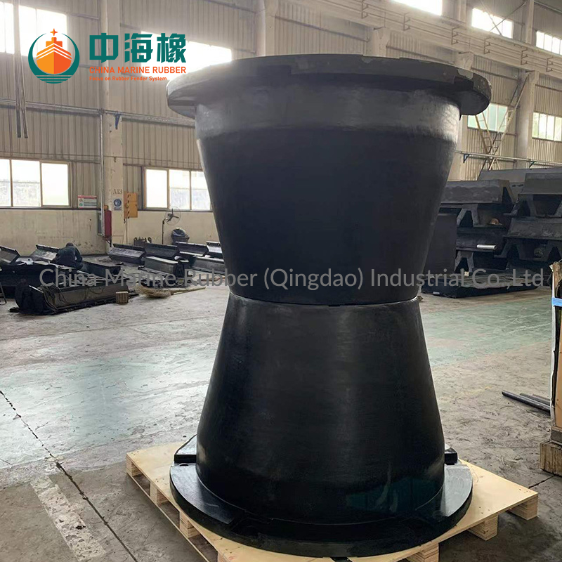
Cell fenders possess a distinct circular base and cone-like cylindrical geometry. This specific structural shape prevents early buckling under heavy asymmetric loads. It ensures highly predictable RF throughout the entire compression cycle. Older cylindrical profiles often collapse unpredictably under extreme pressure. The cell design maintains structural integrity even under massive strain. This stability translates directly to safer daily berthing operations.
The 800H (800mm height) specification hits a recognized engineering sweet spot. It suits mid-sized bulk carriers and large Ro-Ro vessels perfectly. It provides sufficient standoff distance between the steel hull and the concrete pier. It also manages moderate-to-high berthing velocities effectively. Smaller profiles lack the necessary depth for heavy impacts. Larger profiles consume too much valuable space on tight quays. The 800H size balances geometry and impact performance beautifully.
Vessels rarely berth perfectly parallel to the quay wall. Wind, currents, and tug operations cause complicated approach angles. Longitudinal and transverse movements skew the delicate EA/RF balance significantly. They introduce dangerous shear stresses into the solid rubber core. Unchecked shear forces can tear the rubber body entirely. You must account for these multi-directional forces during the engineering phase.
Friction reduction solves the dangerous shear stress issue reliably. Specifying an 800H Super Cell Rubber Fender with PE Pad adds a vital component. Ultra-High Molecular Weight Polyethylene (UHMW-PE) boasts a remarkably low friction coefficient. It consistently measures well below 0.2 in harsh marine conditions. This pad drastically reduces shear loads applied to the rubber body. It ensures the fender compresses linearly during difficult off-angle approaches. It maintains its rated E/R ratio flawlessly under real-world abuse.
Never take manufacturer datasheet EA/RF values at face value. You must actively apply contextual project data to all calculations. Theoretical catalog numbers assume ideal, strictly controlled laboratory conditions. Real environments demand rigorous mathematical adjustments. Failing to adjust these numbers leads to catastrophic system failure. You must adapt theoretical performance to your specific terminal environment.
You must apply three primary correction factors to your engineering calculations:
Velocity Factor (VF): Impact speed directly alters rubber compound stiffness. Faster impacts increase both the dynamic stiffness and the resulting RF.
Temperature Factor (TF): Rubber stiffens dramatically in cold climates, spiking the RF aggressively. Conversely, it softens in high heat, decreasing total EA significantly.
Angle Factor (AF): Off-angle berthing compresses the fender unevenly across its face. This non-linear compression degrades overall energy absorption capacity fast.
Common Mistake: Relying solely on catalog values without applying the Angle Factor (AF). This often results in an undersized system failing during routine angular operations.
Credible procurement requires strict adherence to PIANC 2002 standardization guidelines. Vendors must supply legitimate type-approval certificates for their rubber compounds. They must offer empirical test data strictly adhering to PIANC testing protocols. PIANC ensures accurate, unbiased reporting for all Rubber Fenders globally. It eliminates dangerous discrepancies between competing manufacturer claims. Always demand fully documented PIANC test results before purchasing.
Managing raw reaction force represents only half the engineering challenge. You must carefully translate RF into acceptable Hull Pressure. Engineers typically express this vital metric in kN/m². Different vessel classes feature vastly different hull plating strengths. You must ensure the distributed force never exceeds the hull's limits.
A bare rubber body cannot distribute heavy loads alone safely. The 800H rubber body requires a tight pairing to a steel frontal panel. Engineers design this closed-box steel frame to be extremely rigid. This frontal frame distributes the concentrated RF evenly across the vessel's hull. It prevents localized hull yielding during severe angular impacts. It acts as the necessary intermediary between ship and rubber.
Proper installation directly impacts the long-term survival of the system. Chain tensioning remains an absolutely critical installation step. You must install and meticulously tune weight, tension, and shear chains. These heavy chains support the massive steel frontal frame. They protect the delicate 800H rubber body from tearing under eccentric loads.
Chain Element | Primary Design Function | Critical Installation Focus |
|---|---|---|
Weight Chains | Support the heavy dead weight of the steel frontal frame. | Must remain taut when the fender rests at zero deflection. |
Tension Chains | Limit outward expansion of the compressed rubber body. | Set to engage just before maximum rated tensile stress occurs. |
Shear Chains | Prevent dangerous lateral displacement during angled berthing. | Require precise, symmetric tensioning across the entire panel face. |
Best Practice: Inspect chain tension every six months. Environmental wear and constant impacts loosen mounting shackles over time.
Start by verifying the exact vessel Displacement Tonnage (DT). Map this crucial figure against expected berthing velocities at your port. Consider local water currents, prevailing winds, and available tug assistance. These variables determine the absolute maximum kinetic energy the system will face.
Carefully audit the structural limits of your existing berthing dolphin. If planning a new quay wall, consult the structural engineering models. Ensure the peak RF remains safely below the concrete yielding threshold. The fender must yield long before the concrete pier ever cracks.
Compare the physical durability of high-grade marine rubber against cheaper alternatives. Assess how well the compound resists ozone, UV light, and seawater degradation. Prioritize the wear resistance of the UHMW-PE pad specifically. A highly durable pad extends the functional lifecycle of the entire unit. It achieves this without compromising impact performance.
Before finalizing any bill of materials, demand project-specific performance curves. Ask your suppliers to generate specific deflection versus EA/RF graphs. They must adjust these performance curves for your specific site conditions. This guarantees the selected unit performs exactly as required on day one.
Selecting the right marine fender system serves as a rigid exercise in risk management. You cannot afford to leave kinetic energy dissipation to chance. Prioritizing a high E/R ratio protects both the marine infrastructure and the vessels it serves. The 800H cell design provides the perfect geometric foundation for this heavy-duty task.
Always anchor your procurement decisions in verified PIANC testing protocols. Optimize your system using low-friction PE pads to mitigate damaging shear forces. Review your local environmental variables meticulously to apply accurate correction factors. By enforcing these rigorous engineering standards, terminal operators ensure safe docking operations for decades.
A: A good E/R (Energy Absorption to Reaction Force) ratio indicates a highly efficient fender design. Higher values mean the fender absorbs more kinetic energy while transferring less destructive force to the pier. Cell profiles typically offer superior E/R ratios compared to standard cylindrical models.
A: Cold weather causes the rubber compound to stiffen significantly. This stiffening increases the Reaction Force (RF) generated during impact. Engineers must apply a specific Temperature Factor (TF) multiplier during the design phase to account for this spike and prevent structural overload.
A: An Ultra-High Molecular Weight Polyethylene (UHMW-PE) pad provides a low-friction contact surface. It reduces hull friction as the vessel moves vertically or horizontally. This mitigates destructive shear forces on the rubber core, ensuring it compresses properly without tearing.
A: Yes, they accommodate angular impacts well. However, angular compression reduces total Energy Absorption capacity. You must calculate and apply an Angle Factor (AF) correction to guarantee safe operating margins during non-parallel vessel approaches.