Views: 0 Author: Site Editor Publish Time: 2026-08-01 Origin: Site


Marine infrastructure design carries incredibly high stakes. Port engineers face complex kinetic challenges daily. Miscalculating berthing energy easily leads to premature system failure. You risk catastrophic structural damage to the pier. Vessel hull breaches remain a constant threat. Theoretical models assume parallel berthing. However, real-world operations rarely match these clean mathematical models. Vessels almost never approach a berth perfectly parallel. Wind gusts disrupt navigation. Tidal currents push ships laterally. Tugboat maneuvering introduces slight angular variations. This creates a highly specific challenge for port authorities. We must design marine fendering systems to absorb extreme asymmetric forces reliably. This article serves as a technical decision framework. It guides engineers through evaluating modern fendering solutions. You will learn how real-world vessel approach dynamics dictate design requirements. We will explore how angular impacts shift performance metrics. You will understand why conical geometries handle these complex stresses efficiently.
Angular Impact Shifts Performance: Berthing angles greater than 3 degrees significantly alter the energy absorption and reaction force metrics of standard marine fenders.
Geometry Dictates Resilience: The conical geometry of a cone fender makes it inherently more stable against shear forces and extreme angular compression compared to legacy cylindrical or cell designs.
Specification Requires Correction Factors: Accurate design requires applying industry-standard angular correction factors to baseline fender performance curves.
Testing Mitigates Risk: Evaluating a Super Cone Fender requires verifiable factory acceptance testing (FAT) based on PIANC or CDIT guidelines to ensure real-world compliance.
Theoretical parallel berthing rarely happens in active commercial ports. Operations face unpredictable crosswinds and strong tidal currents. Tugboat assistance varies based on local conditions and operator skill. Furthermore, modern container ships feature highly pronounced bow flares. These environmental and architectural factors guarantee ships approach the quay at an angle.
This non-parallel approach fundamentally alters kinetic energy transfer. During an angled approach, energy concentrates on a much smaller contact area. The vessel hull strikes one specific edge of the fender system first. This drastically increases localized pressure on the frontal panel. It also unevenly compresses the rubber body behind it. An impact meant for a massive surface area focuses entirely on a narrow geometric point.
Berthing angles typically range from 3 degrees to over 10 degrees. These angles introduce complex simultaneous forces. The system experiences direct axial compression alongside severe lateral shear forces. Inferior rubber structures often buckle under these dual stresses. Legacy cylindrical systems excel under purely direct compression. However, they fail rapidly when twisted laterally by a moving hull.
Failing to specify infrastructure for approach angles introduces severe operational risks. You might experience sudden blowout during a heavy storm. Even minor angular miscalculations cause accelerated wear on internal rubber matrices. Unchecked shear forces rip mounting bolts from concrete abutments. Ultimately, underspecifying creates unsafe mooring conditions for operators and cargo vessels alike.
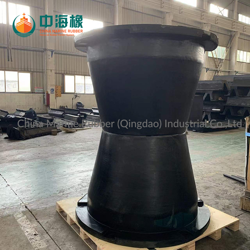
Addressing angular impact requires a specific architectural solution. Engineers developed the cone fender explicitly to handle dynamic multidirectional forces. Its structural design eliminates traditional weak points found in older marine barriers.
We can observe several distinct structural advantages:
Symmetrical Load Distribution: The geometry forces stress evenly down the rubber body.
Wide Mounting Base: A larger diameter at the wall side prevents tipping under lateral loads.
High Deflection Ratio: The unit can safely compress to a fraction of its original height without internal tearing.
Its flared shape delivers exceptional deflection capabilities. These units can safely compress up to 72% of their original height. Crucially, they maintain a stable footprint on the quay wall during maximum compression. This wide base prevents the unit from detaching under extreme off-center pressure.
A properly engineered Super Cone Fender actively resists destructive shear forces. When a ship hull applies load asymmetrically, the conical body distributes the stress downward efficiently. It remains entirely stable without buckling sideways. This specific geometry absorbs kinetic energy efficiently even when twisted by a dragging hull.
Performance degradation under angular impact varies wildly among legacy designs. Traditional cell fenders lose significant energy absorption capacity at angles exceeding 5 degrees. Their straight vertical walls buckle unpredictably under shear stress. Conversely, Cone Fender models maintain a highly efficient energy-to-reaction-force ratio. They barely lose structural integrity or absorption capacity even at steep 10-degree approach angles.
Translating raw vessel approach data into actionable specifications requires careful analysis. You must evaluate multiple structural dimensions to protect the infrastructure effectively.
First, engineers must apply angular correction factors. Manufacturer catalogs typically list baseline performance values based on zero-degree parallel impacts. You cannot use these baseline numbers directly for real-world port design. You must adjust them using PIANC-derived correction factors. These factors decrease the theoretical energy absorption based on your design berthing angle.
The chart below illustrates typical angular correction variations across different rubber geometries.
Fender Type | Energy Absorption at 0° | Energy Absorption at 5° | Energy Absorption at 10° |
|---|---|---|---|
Standard Cell Design | 100% | 90% | 75% |
Conical Design | 100% | 98% | 95% |
Next, consider the steel frontal panel design. You must balance the maximum berthing angle against vessel hull pressure limits. This calculation dictates the exact sizing of the closed-box steel frame. It also determines the thickness of the UHMW-PE surface pads. A correctly sized panel prevents dangerous hull point-loading during an angled strike. It acts as a rigid shield to distribute uneven pressure safely across the entire rubber unit.
Finally, angular approaches demand robust chain configurations. Angled strikes generate massive lateral and vertical dragging forces. You must engineer properly rated weight chains, tension chains, and shear chains. Weight chains support the massive steel panel. Tension chains restrict outward rebound. Shear chains actively prevent the panel from sliding laterally during an angled approach. They keep the system aligned during dynamic vessel movements.
A severe gap often exists between theoretical catalog specifications and actual field performance. Operators face significant implementation risks if they ignore raw manufacturing realities.
Manufacturing tolerances play a huge role in angular performance. Rubber compound variations directly affect how a unit behaves under maximum angular compression. Poorly mixed carbon black and natural rubber might perform adequately during a straight impact. However, it will tear apart rapidly under intense shear stress. You need extreme consistency in polymer blending.
Verifiable testing remains absolutely critical to infrastructure safety. Engineers must reference established PIANC 2002 guidelines or CDIT testing protocols. Always demand constant velocity testing data from your supplier. Real vessels do not slow down perfectly as they compress the rubber. Therefore, decreasing velocity tests inflate performance numbers artificially. Do not accept theoretical curves or scaled-down static tests.
Environmental factors heavily compound the mechanical stress of angular berthing. Extreme temperature fluctuations harden or soften rubber components unpredictably. Long-term UV exposure degrades surface integrity. Saltwater aging weakens the polymer chains over years of service. These harsh realities require high-grade, highly traceable rubber materials. You must specify compounds engineered specifically for your local climate extremes.
Selecting the right marine infrastructure requires a clear decision matrix. Port operators should follow a structured shortlisting process to mitigate risk.
Analyze Berthing Data: Collect accurate approach velocity and maximum angle data for your specific terminal location.
Identify Geometric Risks: Assess the likelihood of high-shear impacts based on local crosswinds and tidal current conditions.
Compare Geometry Types: Evaluate how different rubber shapes handle your worst-case angular scenarios using verified test data.
Verify Manufacturer Capabilities: Confirm the supplier can perform full-scale factory acceptance testing according to PIANC guidelines.
Vessel fleet profiling forms the absolute foundation of this logic. Your design must accommodate the worst-case berthing angle of the largest design vessel. Large bulk carriers generate massive kinetic energy upon impact. Simultaneously, the system must account for the specific bow-flare characteristics of the smallest expected vessels.
Small ships often strike the panel at much higher points. They also approach at steeper, sharper angles. If the frontal panel extends too far, a small vessel might snag the edge. This edge-loading creates immense torsional stress on the rubber unit. Profiling the entire expected fleet prevents these dangerous mismatches.
As a crucial next-step action, we recommend engaging with manufacturers very early in the design phase. Share your preliminary vessel data immediately. Request project-specific 3D modeling. Ask for dynamic kinetic energy calculations based on varying approach angles. Early technical collaboration prevents costly specification errors later in the construction cycle.
Berthing angle acts as a primary driver of marine infrastructure design. It is never merely a secondary or optional consideration. Failing to account for angular velocity leads directly to catastrophic structural failures.
To ensure terminal safety, always apply verified correction factors to baseline performance data. Select geometries naturally suited to absorb high shear forces. Proper chain configurations and robust frontal panels remain non-negotiable for handling angled strikes safely. Engage technical experts early to profile your vessel fleet accurately.
Specifying the correct Super Cone Fender system bridges the gap between theoretical calculations and real-world safety. When you align actual vessel dynamics with proven conical architecture, you protect the hull. More importantly, you guarantee the long-term viability of the commercial port.
A: Most conical systems safely handle operational thresholds up to 10 or 15 degrees. Performance loss remains minimal within this range. However, the exact maximum angle depends heavily on the specific panel configuration and chain setup used.
A: Conical geometries offer vastly superior stability under angular compression. A straight-walled cell design tends to buckle laterally, losing significant energy absorption. The flared base of a conical unit resists this shear stress, maintaining consistent performance.
A: No, angular correction factors do not apply uniformly. They vary significantly based on rubber compound grade, physical unit size, and specific manufacturer testing data. You must always require project-specific verification and empirical testing data for your exact specification.