Views: 0 Author: Site Editor Publish Time: 2026-08-05 Origin: Site


Specifying a marine fender system demands absolute engineering precision from day one. Under-engineering these massive rubber units risks catastrophic structural failure during a rough berthing operation. Conversely, over-engineering them unnecessarily inflates your baseline project costs. You must gather accurate operational data long before evaluating physical hardware.
This article provides marine engineers, port consultants, and terminal operators a definitive framework. You will discover the exact vessel, berth, and environmental data required to correctly specify a cone fender system. We break down the complex variables dictating kinetic energy, structural alignment, and material compliance.
Complete and accurate data collection remains the critical first step in your procurement journey. You need this information before engaging a manufacturer for detailed design calculations and formal quotes. We will explore how to calculate berthing energy, align hardware to quay geometry, and validate performance metrics against rigorous global standards.
Vessel Data is Fundamental: Precise calculation of berthing energy relies heavily on vessel displacement (DWT), approach velocity, and berthing angle.
Berth Geometry Dictates Design: Tidal ranges, water depth, and the specific quay structure (e.g., dolphins vs. continuous walls) determine the frontal panel size and mounting requirements of the cone fender.
Performance Evaluation: The ultimate goal is achieving the optimal ratio of Energy Absorption (E) to Reaction Force (R) without exceeding permissible hull pressures.
Compliance is Non-Negotiable: All specified data must align with rigorous testing and design guidelines, specifically PIANC 2002 and CDIT standards.
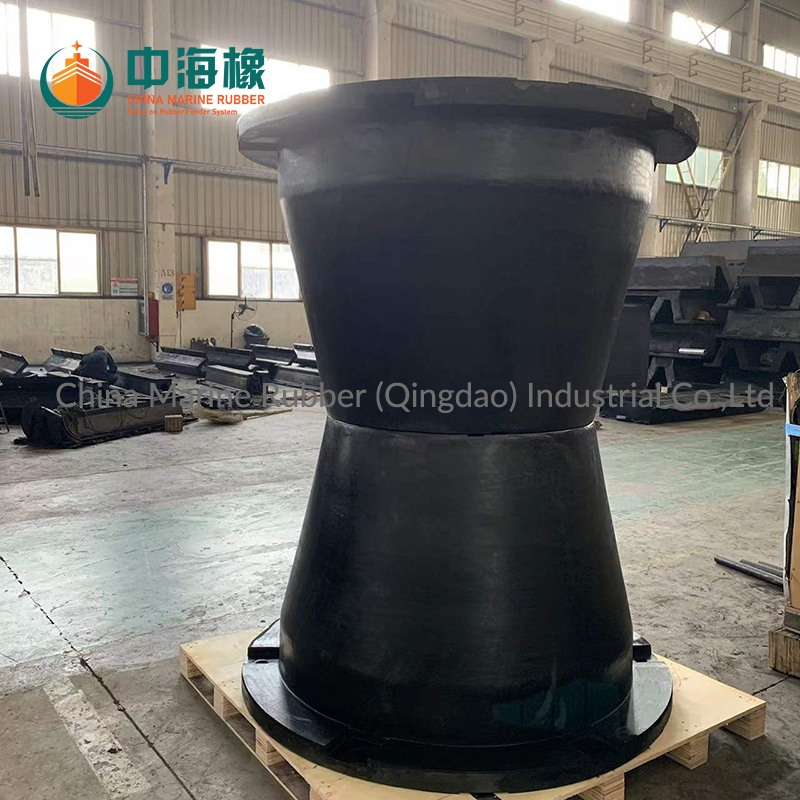
Marine environments impose extreme dynamic loads on port infrastructure. Manufacturers engineer standard and Super Cone Fender models for high-capacity energy absorption in tight spatial footprints. They utilize a conical geometry to compress efficiently under heavy impact. Inaccurate input data heavily compromises this mechanical advantage.
Poor data collection leads to critical specification errors. You might select mismatched rubber grades. This mistake causes premature material wear. It can also transfer excessive force into the concrete berthing structure, resulting in micro-fractures. Ultimately, incorrect specifications endanger both the vessel hull and the terminal foundation.
A correctly specified marine fender system directly maximizes your asset lifespan. It minimizes maintenance downtime across busy operational berths. Proper specifications ensure safe berthing operations under clearly defined operational limits. Marine terminal operators achieve success by aligning their procurement parameters precisely against real-world navigational data.
Kinetic energy calculations dictate the sheer size and capacity of your required fender system. You must capture detailed characteristics of the vessels utilizing the berth. Minor miscalculations here amplify dramatically during the final engineering phase.
You must compile a comprehensive fleet profile. Gather the maximum and minimum Deadweight Tonnage (DWT) or Displacement figures. Fenders must safely accommodate the largest fully loaded vessel without being too stiff for the smallest ballasted ship. Include the Overall Length (LOA), overall beam width, and specific draft measurements. Note both loaded and ballasted conditions. These dimensions inform the added mass coefficient required for accurate kinetic energy modeling.
Approach velocity represents the most critical variable in your entire data set. Kinetic energy increases by the square of the velocity (E = ½mv²). A small jump in approach speed exponentially increases the energy load.
Assess the difficulty of the navigational approach.
Record historical data on prevailing weather conditions affecting pilotage.
Document whether vessels maneuver independently or use tug assistance.
Define both normal and abnormal berthing velocities to establish adequate safety factors.
Vessels rarely dock perfectly parallel to the quay. Standard fender designs typically account for a maximum berthing angle between 6° and 10°. Angular impact significantly affects the compression behavior of the rubber core. It alters the energy absorption efficiency of any Cone Fender. If ships routinely berth at steeper angles, the manufacturer must modify the hardware configuration to prevent shear failure.
Every ship features a specific hull plating strength. You must collect data on the permissible hull pressure for the fleet servicing your terminal. Cruise ships and LNG carriers feature delicate hull structures. They require much lower allowable pressures compared to heavy bulk carriers. This specific pressure metric directly dictates the dimensions of the steel frontal panel attached to the rubber cone. A larger panel distributes the reaction force over a wider surface area, thereby protecting fragile hulls.
The physical geometry of your terminal dictates how manufacturers configure and mount the fender system. You cannot finalize a specification without mapping the exact structural and environmental realities of the berth.
The civil infrastructure determines your mounting footprint. You must identify the specific type of berthing structure supporting the operation.
Open pile structures: These require careful weight distribution. The fender panels often need specialized support chains to prevent excessive vertical sagging.
Gravity walls: These massive concrete structures generally tolerate higher reaction forces. They provide a continuous mounting surface.
Monopile dolphins: These isolated breasting structures offer limited surface area. They demand highly compact fender units capable of massive energy absorption.
Your structure type establishes the permissible reaction force safely transferred into the civil foundation. Exceeding this limit causes structural cracking over time.
Accurate tidal data ensures continuous hull contact. You must provide the Highest Astronomical Tide (HAT) and the Lowest Astronomical Tide (LAT). Compare these water levels against the loaded and ballasted drafts of your design vessels. The resulting data dictates the necessary vertical height of the fender panel. The panel must bridge the gap across all tidal variations to prevent ships from slipping underneath or overtopping the system.
Nature heavily influences abnormal berthing conditions. You must document peak wind speed, maximum wave height, and prevailing water currents at the berth location. These environmental factors push ships off course during the critical final approach. They directly influence the safety factors engineers apply to the kinetic energy calculations. High wind profiles on large container ships require a much more conservative specification buffer.
Gathering data serves one primary purpose: optimizing performance. Marine engineers use your vessel and berth data to balance the two most critical metrics in fender design.
Performance relies on the E/R ratio. We evaluate how the collected data dictates the required Energy Absorption (E) while limiting the allowable Reaction Force (R). The ideal system absorbs massive amounts of kinetic energy without pushing destructive force back into the ship or the quay. Your hull pressure limits and quay structural capacity directly cap the maximum permissible R value.
Manufacturers tweak the chemical compound of the rubber to achieve different performance profiles. Calculated energy dictates whether you require a standard, high, or super-high reaction grade Super Cone Fender.
The following comparison illustrates how different rubber reaction grades perform within the same physical housing footprint.
Reaction Grade | Energy Absorption (E) | Reaction Force (R) | Typical Application Scenario |
|---|---|---|---|
Standard | Baseline | Lowest | Fragile structures, aging quay walls. |
High | +15% to 20% | Moderate | General cargo, modern robust terminals. |
Super-High | Maximum Capacity | Highest | Monopile dolphins, extreme heavy bulk operations. |
Theoretical catalog data rarely matches real-world performance without modifiers. You must apply necessary correction factors to your raw data.
Temperature Factor: Rubber stiffens in cold weather. If your terminal operates in freezing conditions, the reaction force will spike. You must adjust the specification to accommodate this cold-weather stiffness.
Velocity Factor: Rubber responds dynamically to impact speed. Slower impacts often yield different compression resistance than rapid impacts.
Angular Correction Factor: Hitting a fender at an 8° angle reduces its ability to absorb energy compared to a flat, 0° impact. Engineers mathematically derate the fender's performance to account for this angular loss.
You cannot trust theoretical calculations blindly. The marine infrastructure industry relies on strict regulatory frameworks. Your specified data must align with internationally recognized testing protocols.
Manufacturers must validate your input data against established guidelines. The primary global benchmark is PIANC 2002 (Permanent International Association of Navigation Congresses). In some regions, CDIT (Coastal Development Institute of Technology) specifications take precedence. These frameworks dictate exactly how a manufacturer must calculate energy, apply correction factors, and report performance curves. Specifying adherence to PIANC 2002 standardizes the bidding process across multiple suppliers.
Avoid evaluating hardware based solely on theoretical manufacturer catalogs. Catalogs often display idealized performance under perfect laboratory conditions. Require comprehensive Type Approval certificates for the specific fender model. Mandate project-specific performance testing protocols before shipment. Third-party inspectors should witness factory testing to ensure the physical units match your calculated specification data.
Harsh marine environments destroy poor-quality rubber rapidly. UV exposure, saltwater, and ozone cause premature degradation. Ensure your specification outlines acceptable rubber compounding standards. Demand material traceability reports proving the absence of excessive recycled rubber. High-quality virgin rubber compounds maintain their designed E/R ratio for decades.
Once you compile your operational data, you transition into the active procurement phase. You must present this data cleanly to potential suppliers.
Consolidate your gathered vessel, berth, and environmental data into a comprehensive Fender Specification Questionnaire. This standardized document acts as your single source of truth. It removes ambiguity during the initial engineering discussions. A complete questionnaire prevents suppliers from making dangerous assumptions about your terminal conditions.
Submit your data to tier-one suppliers. Expect robust technical support in return. A reputable engineering team will provide 3D CAD modeling of the proposed system integrated onto your specific quay structure. They will return detailed kinetic energy calculations proving their selected model meets your requirements. They should also provide a structural panel analysis validating that the steel frontal panel will not deform under maximum allowable hull pressure.
Do not finalize your civil engineering drawings before verifying your fender sizing. Download a standardized data collection sheet today. Submit your precise project parameters to an engineering team for a preliminary fender sizing calculation. Early collaboration guarantees your structural design accommodates the necessary mounting footprints.
Specifying marine berthing equipment remains an exact science entirely dependent on the quality of your input data.
Accurate vessel displacement, approach velocities, and tidal ranges prevent disastrous under-engineering or costly over-engineering.
Translating operational data into kinetic energy calculations reveals the necessary E/R ratio and optimal rubber reaction grade.
Validating manufacturer proposals against PIANC 2002 guidelines ensures physical performance matches theoretical expectations.
Partnering with an engineering-focused manufacturer early in the data-gathering phase mitigates significant project risks.
A: Exceeding the design berthing angle causes significant angular performance loss. The rubber core compresses unevenly, drastically reducing its energy absorption capacity. This localized stress can shear the rubber away from its steel mounting flanges, leading to catastrophic system failure and structural damage.
A: A super cone system boasts a much higher footprint-to-performance ratio. Its conical shape deflects more efficiently, requiring a smaller mounting area for the exact same energy absorption. You must provide highly accurate concrete structural capacity data, as the reaction force concentrates into this smaller base footprint.
A: General cargo vessels typically tolerate hull pressures ranging from 150 to 200 kN/m². However, this is merely an industry average. You should always consult the specific fleet data and structural drawings of the actual vessels berthing at your terminal to verify exact limits before finalizing panel sizes.
A: Approach velocity dictates the system size due to the kinetic energy formula (E = ½MV²). Because velocity is squared, even a minor miscalculation in approach speed exponentially increases the required energy absorption. Underestimating this speed guarantees the specified fender will be undersized and prone to failure.